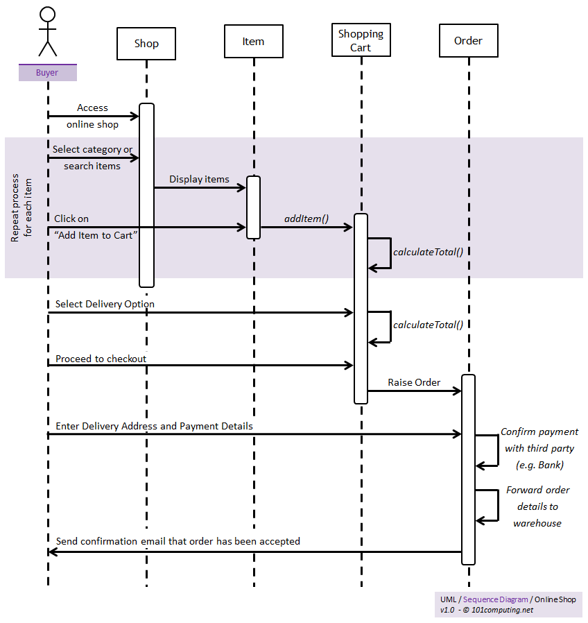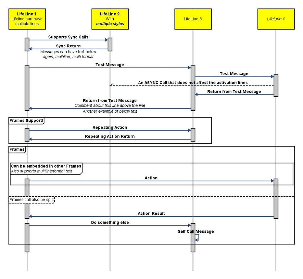

Horizontal arrows show the messages exchanged between the objects. This lifeline represents the object’s existence in the time period being captured. The diagram shows how objects in the system exchange messages and which objects are active at any particular time.Įach object is shown at the top of the diagram and each has a lifeline that descends vertically from its center. Sequence diagrams can also be called event diagrams or event scenarios.
#Sequence diagram uml software
UML diagrams are generally used when designing software and databases to make sure that the system will work as required and to reveal potential problems before building the final product.Ī sequence diagram models the interactions between objects in a system in sequential order over time. Sequence diagrams are one of the 14 diagram types that can be created using the Unified Modeling Language (UML). Notice how an object lifeline has been used to represent the Insufficient Funds extension use case, which (when triggered) requires no further explanation at this level because there should be an entirely separate sequence diagram showing the behavior of the extension use case.What are sequence diagrams and what are they used for? The message label text describes the behavior that the message sender is requesting from the receiver.Ī Message to Self loops back from an Object Lifeline to itself, to show that the business entity or object performs some internal behavior.Ī Message (return) is a dashed message line showing that control is returned to the originator of a message.Ī Constraint is a UML construct showing (for example) that one behavior constraint may not be available in all UML tools and all UML versions, so you may have to use another diagram element – such as a simple note – to indicate this behavior. Messages may be sent to or from an object lifeline in strict sequential order from the top of the lifeline to the bottom.Ī Message from one Object Lifeline to another is indicated by a horizontal line with an arrowhead showing the direction of the message. Our subsequent worked example will utilize the following diagram elements that should be available in most if not all UML tools.Īn Object Lifeline is a vertical line headed by the name and / or classifier type of a business entity or software object. The number and type of diagram elements will vary according to the UML diagramming tool, the version of UML, and the context in which the diagram is to be used.

The sequence diagram is arranged in the form of a strict top-to-bottom timeline of interactions – or message exchanges – between business entities or software objects. This diagram therefore helps with the transition from non-object oriented activity diagrams and use case diagrams to the object-oriented paradigm of modern software development. In this installment we progress from the UML Use Case Diagram to the UML Sequence Diagram.Ī UML Sequence Diagram is used most commonly to show the realization of a use case in terms of interactions between business entities or software objects.
#Sequence diagram uml series
This series of articles is designed to present the set of core UML diagrams in a way that emphasizes the important relationships between the different diagrams and the logical progression from one diagram to another.


 0 kommentar(er)
